#Avrisp mkii programmer pinout software#
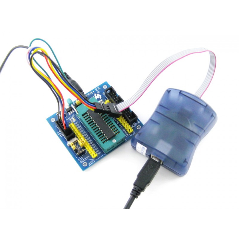
The software side turned out to be a lot trickier, and I’d like to take a little more time to work out the best way to do things. This flexibility will in fact turn out to be quite convenient when dealing with direct-power vs boost-power versions of the JeeNode Micro. Note the sixth wire (providing or sensing VCC power), which goes to either +3V or PWR on the main header. Here is the hookup, using 2×3 long header pins to connect the 2 female ends together:Īnd here’s the breadboard side of things, in close-up: The 2×3 to 6-pin (actually 5-pin) header was constructed from an Extension Cable. In my case, I wanted to use the modified AVRISP mkII programmer, so I’ve set up a little cable + breadboard hack, as follows: For reference, here is the ISP header pinout as most ISP programmers expect it: Adjustable ISP programming speed (50Hz to 8MHz SCK frequency) USB 2.0 compliant (full speed, 12Mbps) Powered from USB, does not require external power supply. It’s just a 4-pin header, with GND and VCC obtained from the 8-pin header on the side of the board. Supports target voltages from 1.8V to 5.5V. I’ll have a lot more to tell about this in a future weblog post, but for now let’s just focus on getting a new sketch into the ATtiny84 chip!Īs mentioned yesterday, there is no longer a standard 2×3 ISP header on this board. By default the 10-pin header connector is mounted. However, note that only one cable should be con- nected, and used, at any given time. Use the one that match the pinout of the target ISP connector.

AVRISP is delivered with one 6-wire and one 10-wire ISP cable. how it deals with the SPI bus during ISP programming (don’t you love those silly acronyms?). Figure 3-2 shows the pinouts for the 6-pin and 10-pin ISP connectors. The new JeeNode Micro v3 announced yesterday does some very subtle things w.r.t.


 0 kommentar(er)
